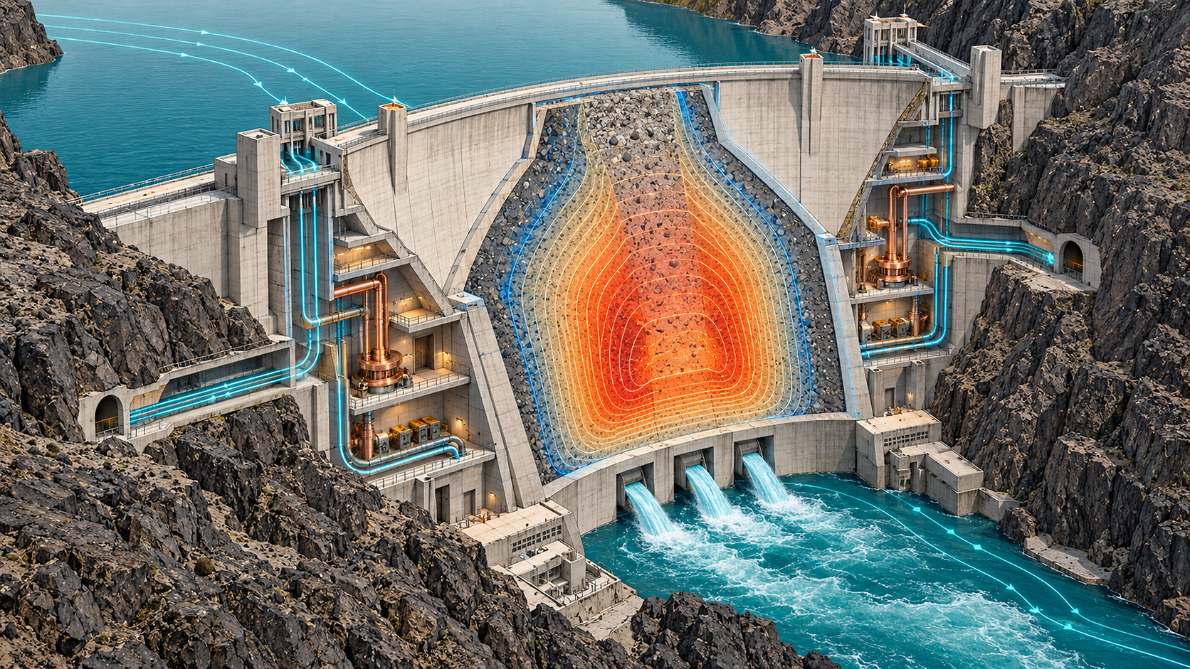
When mass concrete cures, the chemical reaction binding water and cement releases an immense quantity of heat. In ordinary structural slabs, this thermal energy dissipates harmlessly into the surrounding atmosphere, but at the scale of Hoover Dam, placing more than three million cubic yards of concrete in an arid desert canyon created a severe physical dilemma. Without intervention, Fourier conduction dictated that the interior of the giant structure would take well over a century to cool to ambient canyon temperatures. As that trapped thermal mass gradually cooled, uneven volumetric shrinkage against the rigid volcanic canyon walls would generate tensile stresses far exceeding the tensile strength of the concrete, fracturing the dam from within. The solution devised by the United States Bureau of Reclamation was an unprecedented active refrigeration network: dividing the barrier into thousands of interlocking columnar blocks, threading each five-foot lift with thin-walled steel piping, and flushing millions of gallons of river and chilled water through the mass before grouting the contracted joints into an impervious, monolithic arch.
The Exothermic Burden of Mass Concrete
Hydraulic cement does not set by drying; it hardens through a series of exothermic chemical reactions collectively known as hydration. When water is introduced to Portland cement powder, calcium silicates and aluminates dissolve, react, and precipitate into interlocking crystalline structures of calcium silicate hydrate and calcium hydroxide. In standard building construction, where structural elements have thicknesses measured in inches or a few feet, the heat generated by these chemical bonds freely conducts to the surface and radiates away into the atmosphere without causing severe internal temperature spikes. However, in mass concrete structures where the volume-to-surface-area ratio is exceptionally large, the physics change dramatically.
The core of a colossal gravity barrier acts as an effective thermal insulator. Concrete possesses a notably low thermal conductivity, meaning heat generated deep inside a massive pour remains trapped for extraordinarily long periods. During the initial design phase of Hoover Dam in the late 1920s, engineers realized that pouring 3.25 million cubic yards (2.48 million cubic meters) of concrete into Black Canyon would trap an enormous quantity of chemical energy. Calculations indicated that the core temperature would rise by 50 to 70 degrees Fahrenheit (28 to 39 degrees Celsius) above its placement temperature within days of casting.
Without an engineered intervention to strip this energy away, the mass would have reached temperatures exceeding 130 to 140 degrees Fahrenheit (54 to 60 degrees Celsius). Because the exterior faces cool rapidly against the ambient air and water while the interior remains intensely hot, sharp thermal gradients develop. The cooler outer shell attempts to shrink around an unyielding, thermally expanded core, generating severe surface tension that inevitably leads to deep, structurally debilitating thermal fractures. Managing this hydration heat was not an aesthetic consideration; it was the fundamental prerequisite for structural survival.
The Physics of Trapped Thermal Energy
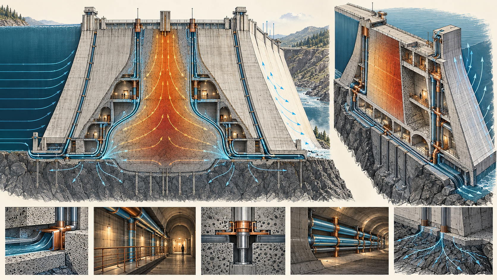
The rate at which thermal energy moves through any solid medium is governed by Fourier's law of heat conduction, which states that local heat flux is directly proportional to the negative gradient of temperature. In concrete, thermal diffusivity—the property combining thermal conductivity, specific heat capacity, and density—typically ranges between 0.03 and 0.05 square feet per hour (0.0028 to 0.0046 square meters per hour). Because heat dissipation time scales with the square of the distance thermal energy must travel to reach a boundary, doubling the thickness of a concrete wall increases the required cooling time by a factor of four.
Hoover Dam was designed with a base thickness of 660 feet (201 meters) and a crest width of 45 feet (13.7 meters), standing 726 feet (221 meters) above the bedrock of the Colorado River. Bureau of Reclamation mathematical models directed by engineers such as C. H. Howell and R. E. Glover revealed alarming conclusions when these geometric dimensions were input into classical transient heat diffusion equations. They determined that if the dam were cast as a continuous, uninterrupted mass without artificial cooling, the core would require between 110 and 125 years to cool to the mean annual temperature of the canyon environment.
Over such an extended timescale, the exterior shell would have stabilized decades before the core. As the interior gradually lost its trapped hydration heat over the following century, the core would inevitably undergo volumetric shrinkage. Because the exterior perimeter would already be rigid and fixed against the sheer volcanic walls of Black Canyon, the shrinking core would be placed in intense triaxial tension, ripping the dam apart with wide internal fissures that would destroy its water-retaining capacity and arch-loading capability.
Monolithic Temptation versus Volumetric Contraction
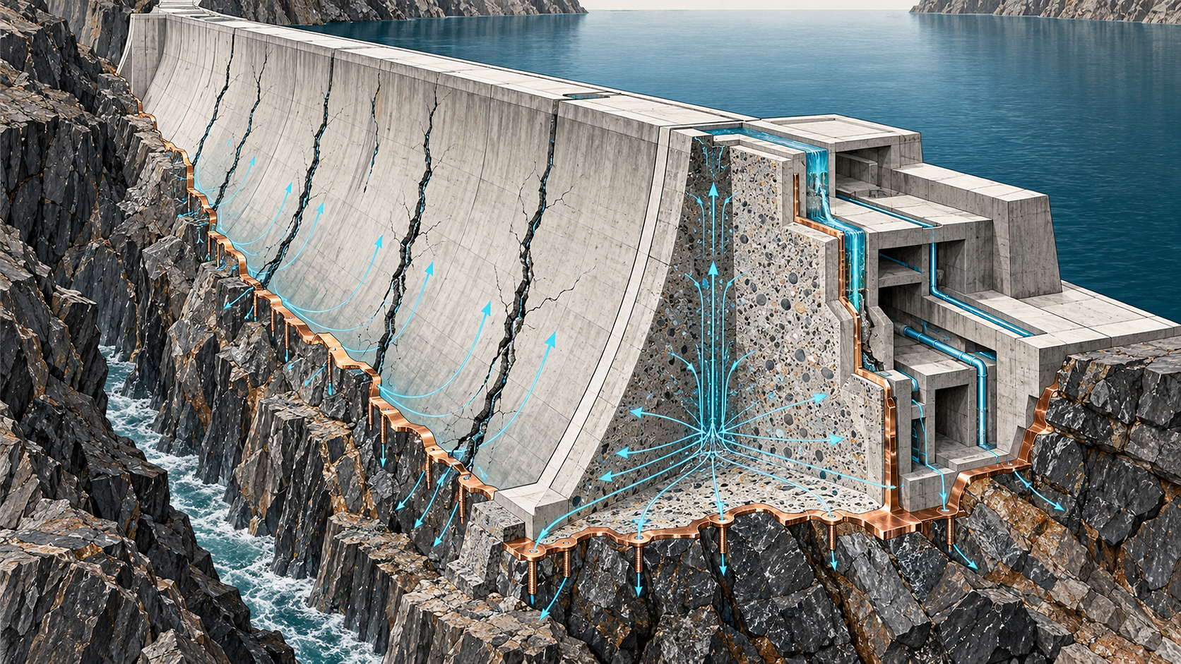
In early twentieth-century dam engineering, the conventional instinct was to pour concrete continuously to create an unbroken, monolithic mass. A single solid stone barrier theoretically eliminated seams where water might seep through under tremendous hydrostatic pressure. However, as the physical height and base thickness of gravity dams climbed to match the demands of major river basins, this monolithic ideal collided directly with the laws of thermal contraction and material elasticity.
Concrete has a linear coefficient of thermal expansion of approximately 5.5 millionths per degree Fahrenheit (roughly 10 millionths per degree Celsius). While this value appears minuscule in laboratory test cylinders, multiplying it across a structure measuring 660 feet across its base produces dimensional shifts measured in inches. If a block of concrete spanning several hundred feet cools by 50 degrees Fahrenheit, it must shorten by several tenths of a foot. If that mass is cast directly against an immovable foundation of basalt and andesite breccia, it cannot freely shorten.
The resulting restrained contraction creates tensile stress proportional to the modulus of elasticity of the material. Because the tensile strength of concrete is notoriously weak—typically only 8 to 12 percent of its compressive strength—the tensile stress induced by even a moderate temperature drop easily exceeds the ultimate tensile strain limit of the material. The dam would crack vertically, parallel to the canyon walls and perpendicular to the upstream face, creating direct conduits for high-pressure reservoir water to penetrate the interior and induce destabilizing uplift pressures.
The Modular Column Architecture
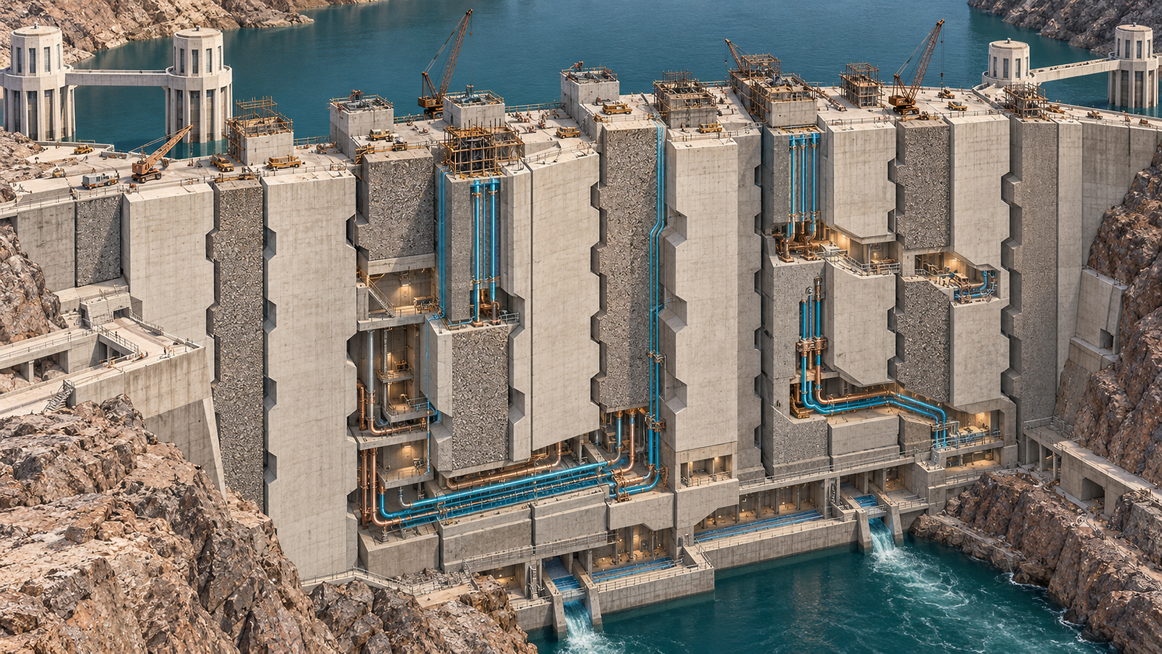
Recognizing that a monolithic continuous pour was mathematically and physically impossible, the Bureau of Reclamation abandoned the traditional continuous placement strategy. Instead, the design team partitioned the massive curved wedge of Hoover Dam into an elaborate, interlocking three-dimensional mosaic of independent vertical columns or blocks. No block was permitted to exceed an area of 50 by 50 feet (15.2 by 15.2 meters) on the upstream side or 25 by 25 feet (7.6 by 7.6 meters) near the downstream face, keeping the horizontal footprint of each discrete element within safe contraction boundaries.
Concrete was placed in successive vertical lifts restricted to an exact height of five feet (1.52 meters). To prevent individual blocks from toppling and to distribute seismic and hydrostatic loads evenly, the vertical faces of the columns were cast with interlocking vertical and horizontal keys. These shear keys were formed as trapezoidal indentations and protrusions in the wood forms, creating a complex mechanical interlock resembling giant puzzle pieces. Adjacent columns were raised at varying schedules, creating a checkerboard pattern across the canyon floor that allowed the perimeter of each lift to radiate a portion of its early heat to the air.
However, compartmentalizing the dam into columns addressed only one-half of the engineering problem. If left to cool naturally, the individual columns would still take decades to stabilize, contracting away from one another and leaving open vertical joints between the blocks. Water would pour through these gaps under high hydrostatic head, preventing the dam from functioning as an arch or transferring compressive thrust into the abutment walls. Active artificial cooling became the essential mechanical bridge needed to bring these columns to final dimension rapidly so they could be fused together.
Evolution of Active Cooling Concepts
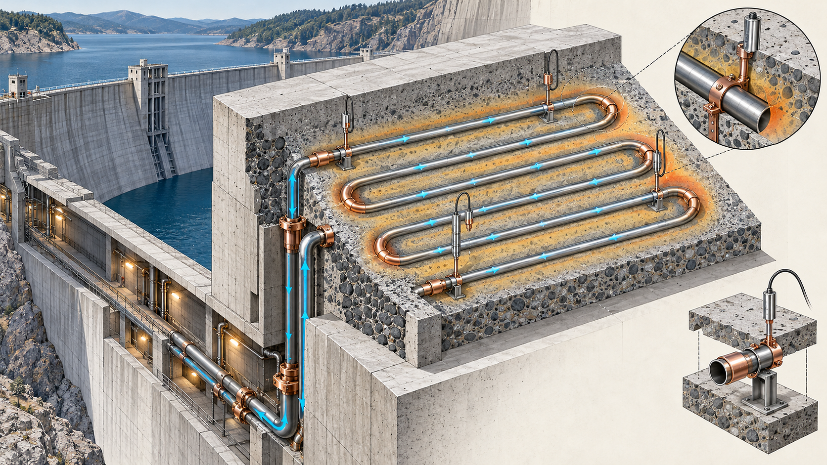
The idea of accelerating concrete cooling by circulating water through embedded conduits had been proposed in embryonic forms prior to Hoover Dam, but it had never been attempted on an industrial scale. Reclamation engineers tested the preliminary physics during the construction of Owyhee Dam in eastern Oregon between 1928 and 1932. At Owyhee, an experimental grid of one-inch steel pipes was cast into a section of the concrete to study heat dissipation rates, pumping losses, and temperature drops under real-world casting conditions.
The Owyhee trials validated Glover’s mathematical models, demonstrating that flowing water could effectively strip hydration heat before peak internal temperatures caused microstructural degradation of the concrete gel. Furthermore, the experiments proved that the thermal gradient between the circulating water and the surrounding concrete could be managed without inducing localized thermal shock. If cold water was introduced too quickly to a hot lift, the steep temperature differential between the metal pipe wall and the concrete would crack the matrix within a few inches of the tubing.
Armed with empirical data from Owyhee, the Reclamation design office in Denver developed a comprehensive cooling plan for Hoover Dam. The scale was unprecedented: rather than an experimental localized array, the entire structural volume of the dam would be fitted with continuous cooling loops. Every single cubic yard of concrete placed in the dam would sit within a few feet of an active heat exchanger, allowing the engineers to dictate the thermal destiny of the massive barrier precisely.
The Thin-Wall Steel Pipe Network
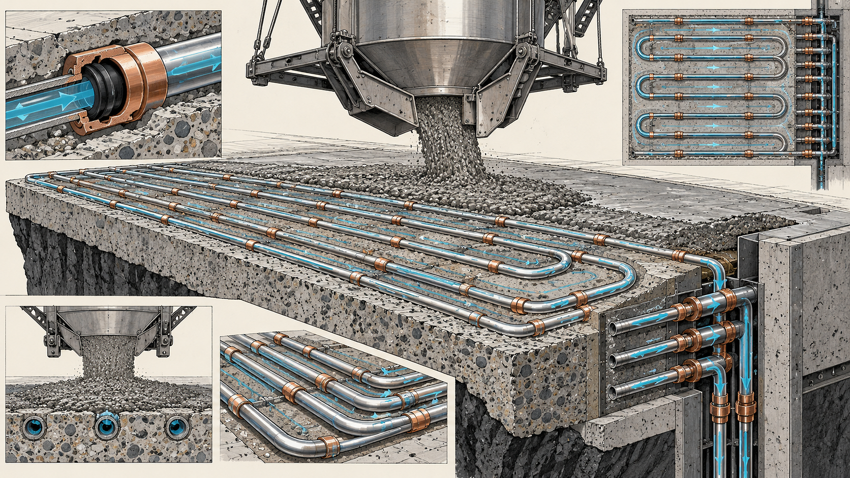
The mechanical backbone of this thermal extraction system consisted of approximately 582 miles (937 kilometers) of 1-inch outside-diameter (25.4 mm) thin-walled steel tubing. The pipe had a wall thickness of only 0.065 inches (1.65 mm), specified to maximize heat conduction across the metal boundary while retaining sufficient tensile yield strength to survive the rough mechanical impacts of concrete placement, vibrator immersion, and foot traffic. Flexible, lightweight tubing was critical because thousands of individual segments had to be handled manually atop freshly poured lifts in the blazing desert heat.
The pipes were laid directly onto the horizontal surface of each five-foot lift once the concrete had taken its initial set and cured for several days. Work crews assembled the tubing in serpentine loops that ran back and forth across the top of each block before terminating at headers in an eight-foot-wide central vertical distribution slot that cut through the dam along its axis. Horizontal spacing between adjacent tubing runs was established at approximately 5 feet 9 inches (1.75 meters) on centers, creating a uniform thermal extraction grid that left no concrete volume more than three feet from a cooling conduit.
To connect adjacent pipe lengths without time-consuming threading, the project utilized special compression-type couplings fitted with rubber gaskets. These joints could be assembled rapidly by field crews and possessed sufficient angular flexibility to accommodate minor deviations in pipe alignment. Before the next five-foot lift of concrete was placed directly over the tubing array, the entire circuit was subjected to hydrostatic pressure testing at 100 pounds per square inch (690 kPa) to confirm that no leaks existed. Concrete was then dumped from eight-cubic-yard bottom-dump buckets suspended from aerial cableways, with crews taking extreme care not to displace or crush the fragile steel lines.
River Water Pre-Cooling Phase
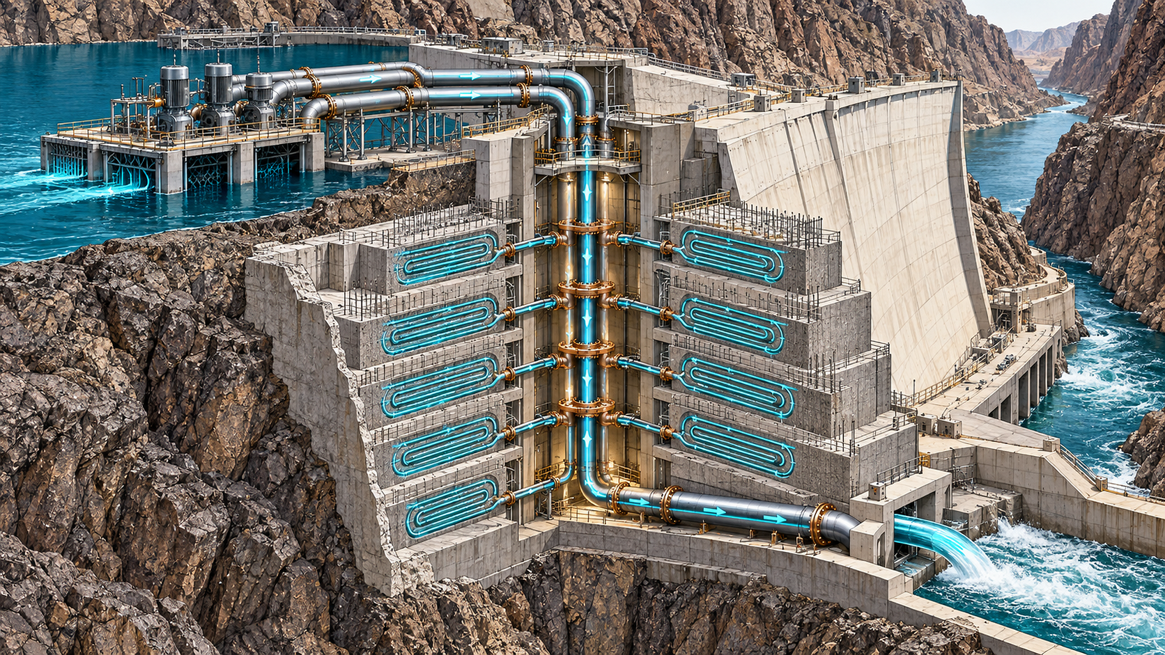
Thermal extraction was executed in two distinct, sequential stages to optimize energy efficiency and control thermal stress. The first stage utilized raw, unchilled water drawn directly from the Colorado River upstream of the cofferdam. Although desert summer river temperatures were warm—often reaching 60 to 80 degrees Fahrenheit (16 to 27 degrees Celsius)—this water was still significantly cooler than the concrete, which climbed toward 130 degrees Fahrenheit (54 degrees Celsius) within days of hydration.
Circulating river water through the embedded loops immediately after the initial curing spike provided a high-capacity thermal sink that absorbed the intense early peak of hydration heat. Pumps located at a temporary river pumping station forced river water through large supply headers down the central slot and into the labyrinth of one-inch block pipes. The cooling circuits were operated continuously, stripping the hottest thermal surge out of the core and carrying the energy back into the river downstream.
This initial pre-cooling stage lowered the concrete temperature to roughly the ambient temperature of the river water over a period ranging from six to twelve weeks, depending on block placement location and seasonal ambient conditions. By using raw river water for the primary extraction, the project saved massive amounts of mechanical refrigeration energy, removing approximately two-thirds of the total excess heat without consuming a single kilowatt of artificial chilling power. Only when the concrete reached equilibrium with the river was the circuit switched to the second, refrigerated stage.
The Ammonia Refrigeration Plant
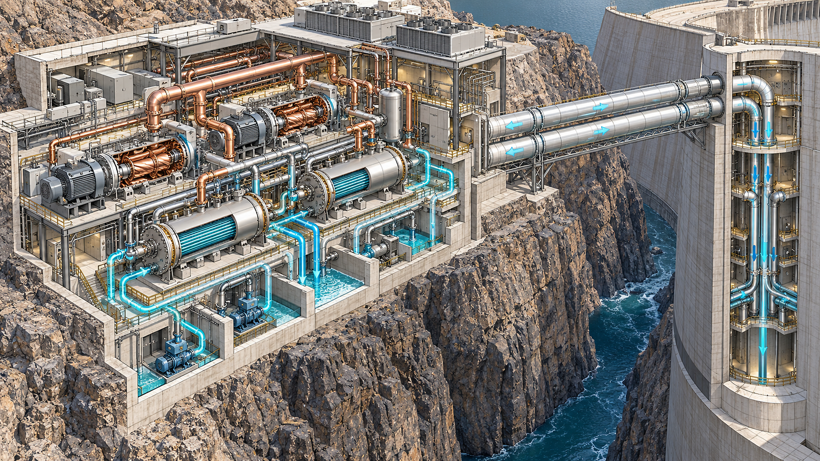
To bring the concrete down to its final design temperature—which had to match or drop slightly below the ultimate mean temperature of the deep reservoir water and surrounding rock—ambient river water was insufficient. Reclamation engineers determined that the concrete needed to be cooled artificially to temperatures between 40 and 55 degrees Fahrenheit (4.4 and 12.8 degrees Celsius), depending on its elevation and depth within the dam. To supply this chilled fluid, the contractor, Six Companies Inc., constructed one of the largest industrial refrigeration plants built up to that era.
Erected on a bench along the canyon wall downstream of the dam, the plant housed three massive, motor-driven horizontal ammonia compressors operating alongside an array of shell-and-tube water chillers. The facility possessed an effective refrigeration capacity of 1,000 tons of ice per 24 hours, an industrial rating meaning it could absorb heat at a rate equivalent to melting 2,000,000 pounds of ice every day. The plant chilled fresh, non-sediment-laden water to between 40 and 45 degrees Fahrenheit (4.4 and 7.2 degrees Celsius) before pumping it into the insulated distribution grid.
Twin insulated 14-inch steel main pipelines carried the refrigerated water from the plant across a suspension bridge and into the central slot of the dam. From these vertical risers, distribution manifolds routed the cold water through the individual block cooling coils at carefully regulated flow rates of approximately three to four gallons per minute per circuit. The warm return water was gathered in complementary header pipes and routed back down to the plant chillers in a closed-loop recirculation cycle, preserving treated water supplies and optimizing thermodynamic efficiency.
Flow Dynamics and Thermal Gradients
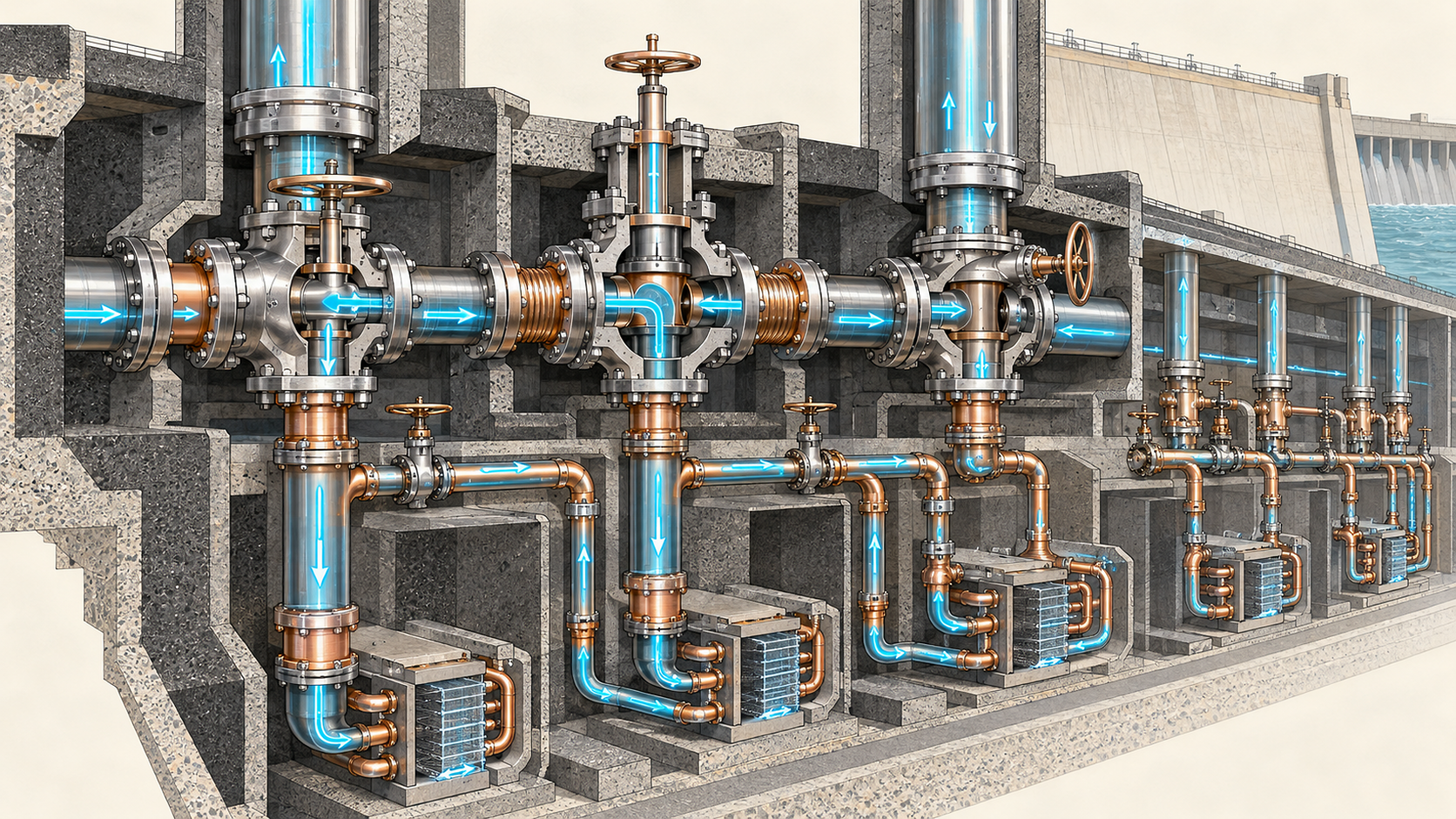
Regulating the flow of coolant through hundreds of active coils required meticulous hydraulic management. If water was pumped through a single loop for too long in one direction, the liquid absorbed heat as it traveled, creating an internal temperature gradient where the concrete near the intake pipe was cooled substantially faster than the concrete near the exhaust end. This differential shrinkage could trigger internal shear cracking between opposite edges of the same column.
To maintain internal thermal symmetry, operational procedures mandated periodic flow reversals. Valves on the header manifolds were manipulated so that every 48 to 72 hours, the direction of water flow through each individual circuit was reversed. By switching the inlet and outlet ports, the temperature gradient along the pipe run was continuously inverted and smoothed, ensuring that both sides of each concrete block cooled at identical average rates.
Furthermore, engineers had to maintain strict limits on the cooling rate itself. Accelerating thermal extraction beyond permissible limits would produce excessive differential strain between the cooling pipe surface and the surrounding concrete mass. Standard operating protocols restricted the cooling rate so that no block dropped more than two to three degrees Fahrenheit (1.1 to 1.7 degrees Celsius) per week. Technicians monitored the temperature of the returning water continuously; an abrupt rise or drop signaled an imbalance in flow distribution or localized blockage in the coil network, prompting rapid valve adjustments.
Low-Heat Cement Chemistry Formulation
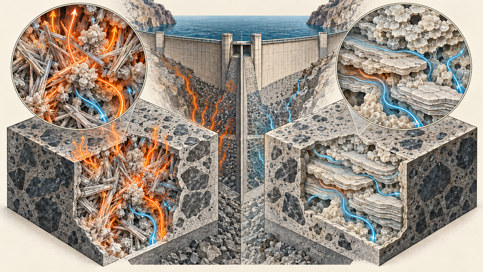
The mechanical pipe system was only half of the thermodynamic solution; the other half was a revolutionary advance in material science. Standard Portland cement available in the early 1930s was formulated primarily for high early strength, characterized by high proportions of tricalcium silicate (C3S) and tricalcium aluminate (C3A). These two chemical compounds hydrate aggressively, releasing the vast majority of their thermal energy within the first 48 to 72 hours after mixing. For mass concrete, this rapid heat surge was an unnecessary hazard.
Under the technical leadership of chemist Raymond E. Davis and the Bureau of Reclamation, a comprehensive testing program was initiated to formulate a customized, low-heat Portland cement specifically for Hoover Dam. The chemical composition was systematically altered: tricalcium aluminate, which generates an immense 207 calories per gram during hydration, was capped at a strict maximum of 7 to 8 percent. Tricalcium silicate was substantially reduced, while dicalcium silicate (C2S), which hydrates very slowly and generates only 62 calories per gram, was increased to become the dominant phase, representing over 50 percent of the cement blend.
This modified chemistry dramatically lowered the peak temperature surge. At seven days of age, the low-heat cement generated only about 60 calories per gram, compared to nearly 100 calories per gram for contemporary standard cements. While concrete cast with this low-heat mix exhibited lower compressive strength during the first two weeks, its long-term strength gain at one and two years actually surpassed conventional mixtures. By slowing the rate of hydration, the chemical heat generation was stretched over months, allowing the cooling pipe network to evacuate thermal energy smoothly without being overwhelmed by an early thermal spike.
Grout Contraction Joints and Monolithic Integration
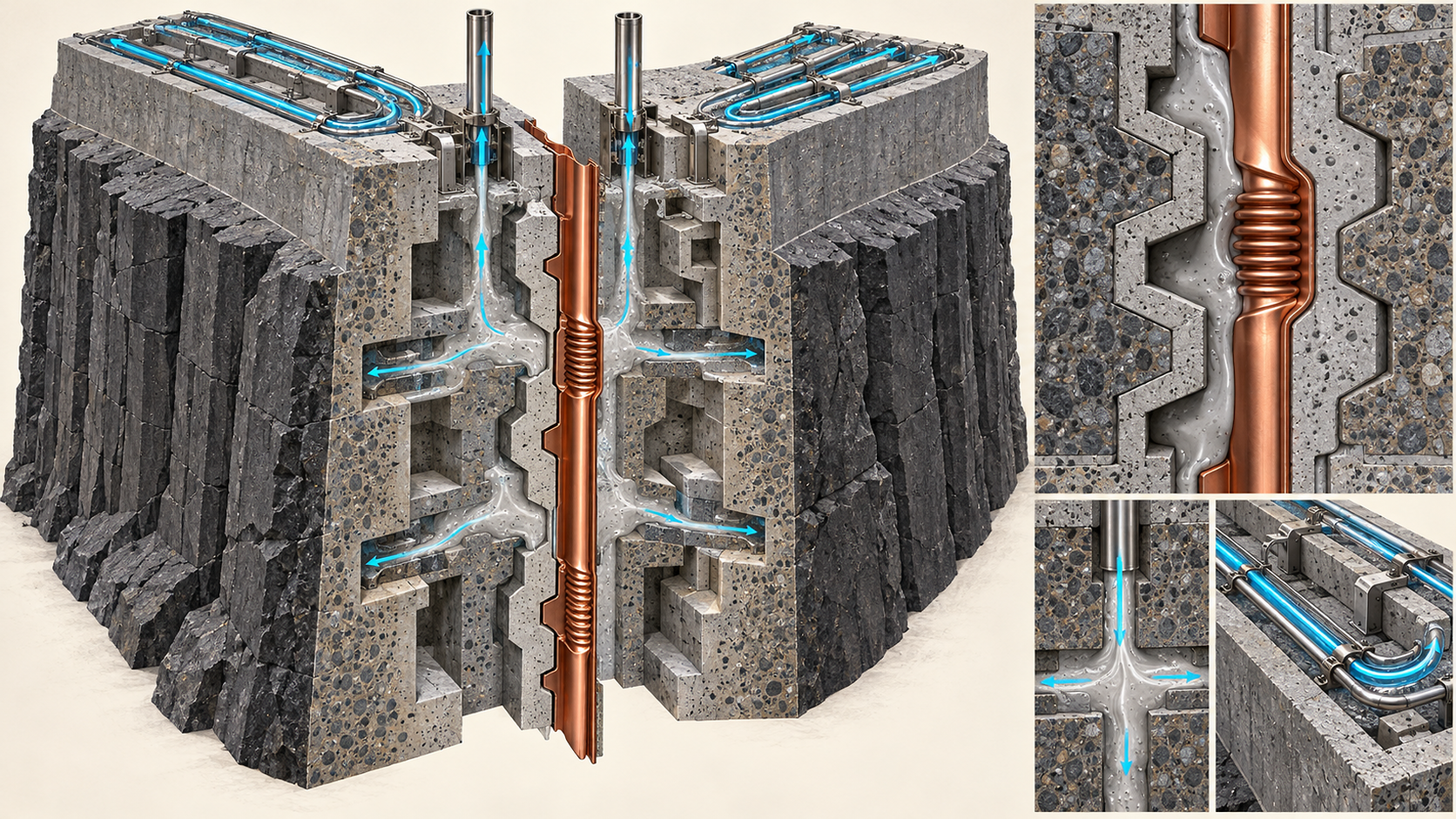
The artificial cooling network served a specific mechanical objective: to bring each independent block to its ultimate contracted dimensions before the reservoir was filled. If the dam were built as isolated columns without post-cooling treatment, hydrostatic pressure would push the columns against one another unevenly, inducing localized crushing along contact points and allowing high-pressure water to rip through the open joints. The blocks had to be cooled until they contracted to their absolute minimum anticipated long-term volume, creating a visible, uniform gap along the vertical joints.
Once resistance thermometers confirmed that a given structural zone had reached its target design temperature—typically between 40 and 50 degrees Fahrenheit—cooling water was shut off. Because each block had contracted, the vertical contraction joints between adjacent columns opened by fractions of an inch, typically between 0.05 and 0.125 inches (1.3 to 3.2 mm). Embedded within these joints during initial placement was an elaborate system of copper waterstops, grout piping headers, and thin metal grout vents designed specifically for this moment.
Crews pumped a fluid slurry of neat cement and water, mixed under exacting water-cement ratios, into the open joints under pressures ranging from 50 to 300 pounds per square inch (345 to 2,070 kPa). The pressurized grout penetrated every square inch of the opening, coating the trapezoidal shear keys and locking adjacent columns together into a solid, monolithic arch. When the grout set, the once-separate columns were unified into a continuous compressive shell capable of transferring hundreds of thousands of tons of hydrostatic water thrust directly into the Black Canyon rock walls without internal tensile cracking.
Structural Integrity and Uplift Management
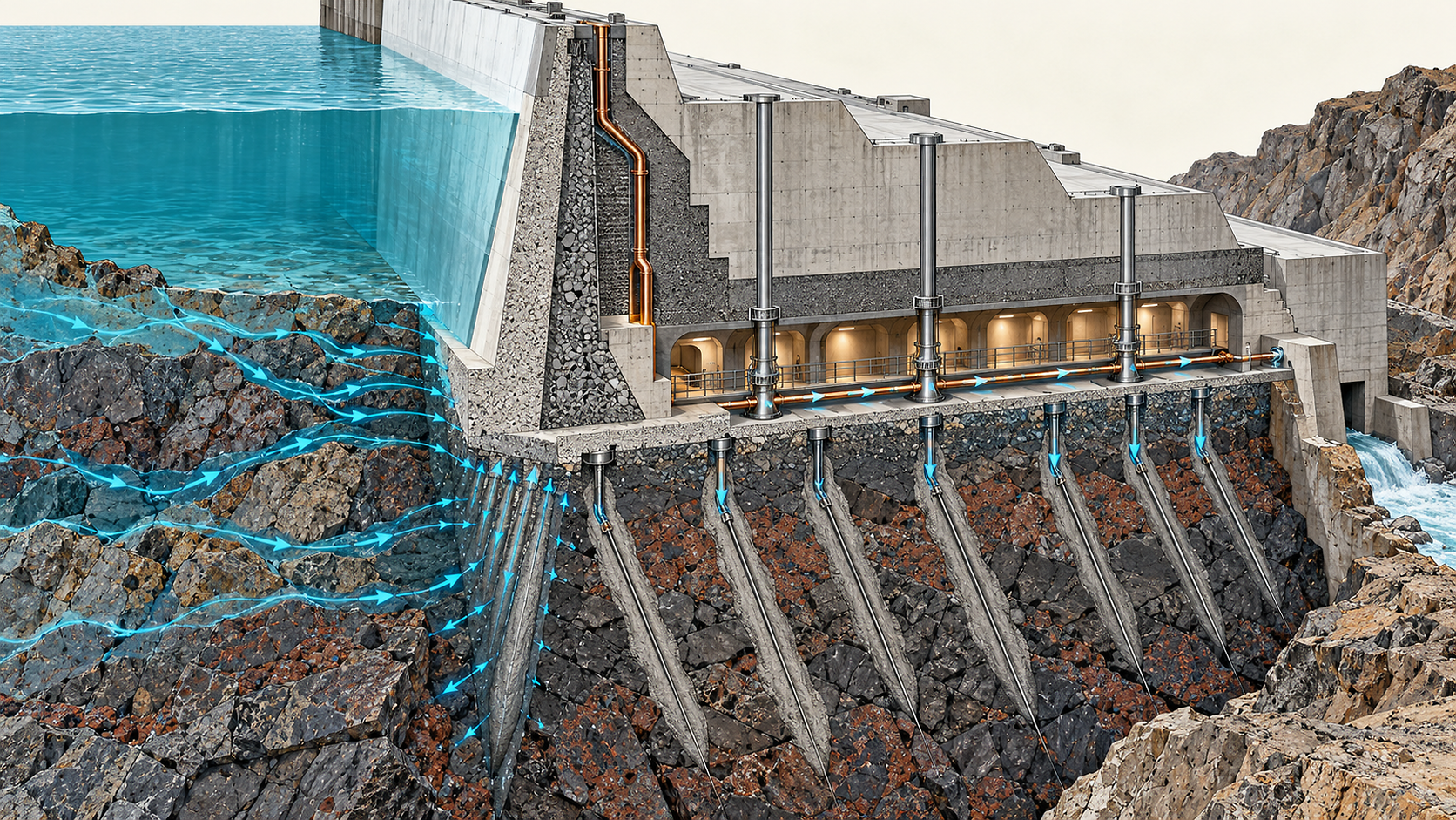
The cooling and joint-grouting sequence played a direct role in protecting the dam against its most dangerous hydraulic enemy: internal uplift pressure. When reservoir water rises behind a concrete barrier, water molecules seek pathways through porous rock foundations and cold joints within the dam mass. If water under pressure permeates horizontal or vertical construction seams, it exerts an upward pore pressure that counteracts the gravity weight of the structure, dramatically reducing its resistance to sliding or overturning.
By cooling the concrete blocks before joint grouting, engineers ensured that the upstream face formed an impervious compression zone under hydrostatic loading. Thermal contraction cracking, which had crippled older gravity dams by providing pathways for reservoir water infiltration, was completely prevented. The monolithic grout seal eliminated vertical pathways, while strict surface cleaning and pneumatic sandblasting between the five-foot lifts ensured that horizontal joints bonded with high shear and tensile cohesion.
To manage any residual seepage that might bypass the upstream grout seal, the interior of the dam was threaded with an extensive network of inspection galleries, porous drainage pipes, and vertical foundation drain holes drilled deep into the rock abutments. Furthermore, a deep high-pressure grout curtain was injected into the foundation rock near the upstream heel. The combination of an uncracked, post-cooled mass, an impenetrable grout curtain, and internal drainage galleries ensured that uplift pressure along the base was safely mitigated, preserving the gravity equilibrium of the entire structure.
Instrumentation and Temperature Monitoring
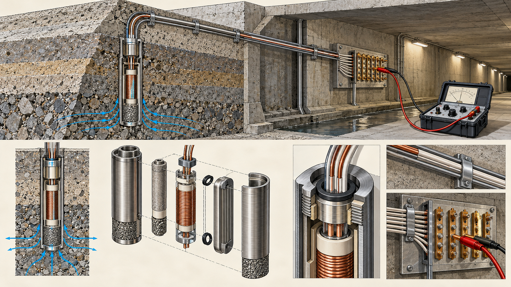
Operating an artificial cooling system across millions of cubic yards of concrete without real-time thermal visibility would have been catastrophic. Over-cooling one section could induce tensile cracking, while under-cooling would leave joints insufficiently open for effective grout penetration. To provide structural visibility, Reclamation engineers installed an unprecedented telemetry array consisting of more than 2,000 embedded electrical resistance thermometers throughout the interior of Hoover Dam.
These sensors consisted of fine coils of insulated copper or nickel wire sealed inside watertight metal casings. The operating principle relied on the linear relationship between electrical resistance and temperature: as the temperature of the concrete surrounding the embedded capsule shifted, the resistance of the metal coil changed proportionally. Calibration tables allowed operators to convert Wheatstone bridge resistance measurements directly into temperature readings with an accuracy of within one-half degree Fahrenheit (0.28 degrees Celsius).
Lead wires from every individual thermometer were routed through the five-foot lifts and bundled into protective conduits that terminated in terminal boards located inside the longitudinal inspection galleries. Daily, technicians walked the damp interior galleries with portable Wheatstone bridge sets, connecting to hundreds of terminals to map the evolving thermal contours of the dam. These empirical measurements allowed the cooling plant operators to modulate chilled water flow through specific block zones, pinpointing blocks that required increased circulation or identifying sectors that were ready for immediate joint grouting.
Pipe Abandonment and Cementitious Sealing
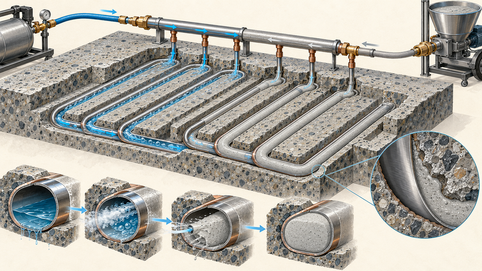
Once a cooling circuit had fulfilled its purpose—bringing its respective concrete lift to the specified temperature and holding it there until joint grouting was completed—the embedded thin-walled steel tubing could not simply be left open. Leaving hundreds of miles of empty, air-filled, or water-filled one-inch voids within the dam would create structural discontinuities, stress concentrations, and potential avenues for internal water migration or corrosion channeling under prolonged hydraulic loading.
The cooling pipes had to be permanently decommissioned and integrated into the solid matrix of the dam. To achieve this, the circuits were disconnected from the chilled water headers, flushed with clean compressed air to blow out all standing cooling water, and thoroughly tested for structural clearance. Grout injection nipples were attached to the pipe terminals located inside the central slot and longitudinal galleries.
High-pressure grout pumps were then connected to the empty tubing loops, forcing a fluid mixture of neat Portland cement, water, and expanding agents through the entire serpentine circuit under pressures of 100 to 200 pounds per square inch (690 to 1,380 kPa). Pumping continued until thick, uniform grout emerged from the exhaust ends, verifying that all trapped air had been evacuated. The lines were then sealed under pressure, encasing the interior of the steel pipes in solid cement stone. This final step transformed the temporary heat-exchanger grid into an inert, permanent component of the mass concrete, restoring complete volumetric solidness to the interior of the dam.
Enduring Legacy in Global Dam Engineering
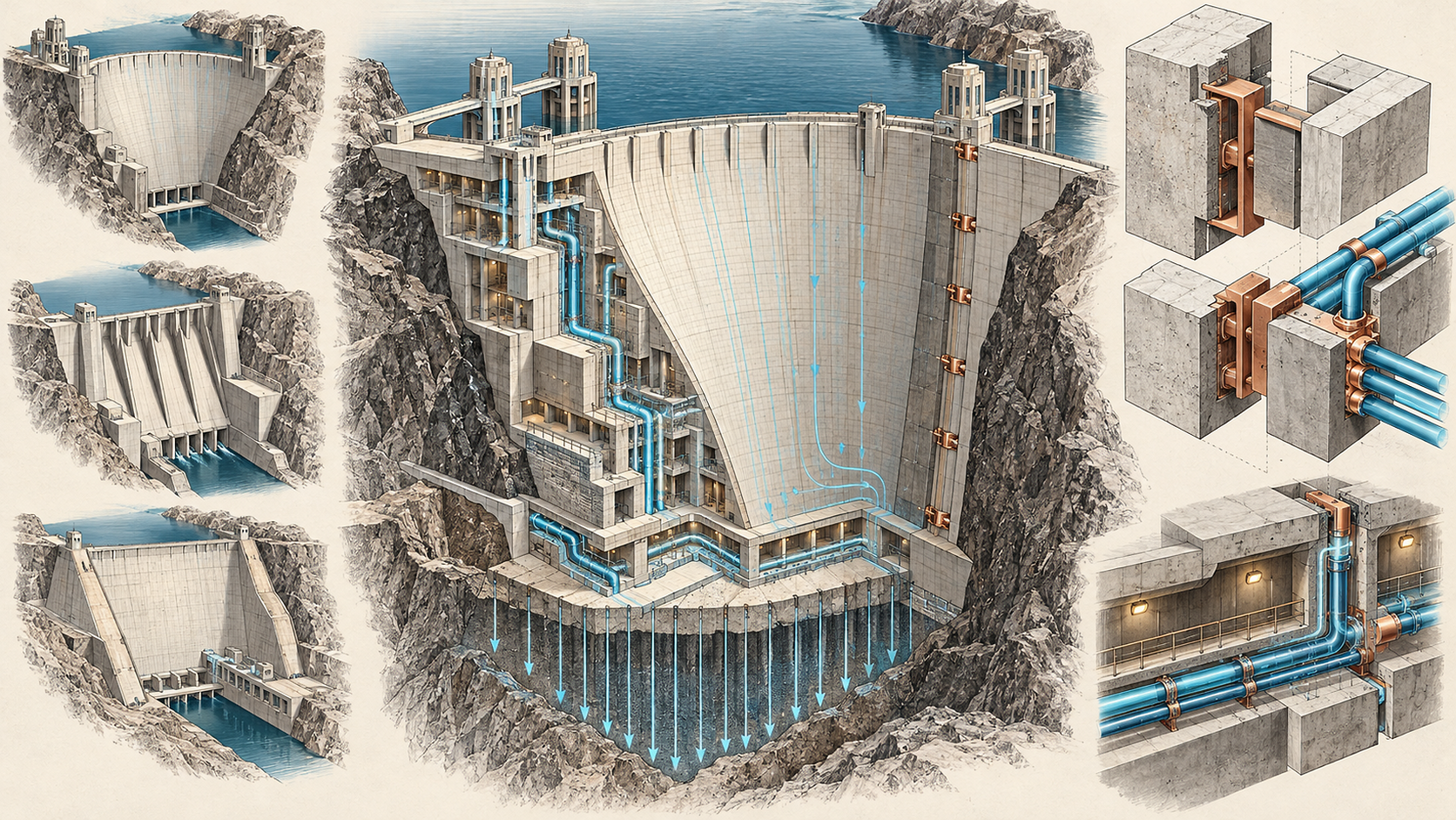
The artificial cooling system at Hoover Dam represented a major turning point in modern civil engineering. Before this system proved successful, the physical size of concrete gravity structures was fundamentally constrained by the slow pace of natural heat conduction and the destructive reality of thermal shrinkage cracking. By transforming mass concrete from an unpredictable, cracking material into an actively controlled thermodynamic medium, Reclamation engineers demonstrated that human structures could be scaled to monumental heights safely and predictably.
The methodologies developed at Black Canyon immediately became the standard specification for subsequent mega-dam projects across the world. Grand Coulee Dam on the Columbia River, Shasta Dam in California, and Glen Canyon Dam on the upper Colorado River all utilized refined variations of the Hoover embedded cooling pipe network, ammonia refrigeration systems, and joint-grouting protocols. Decades later, major international hydraulic projects, including Kariba Dam in southern Africa and Three Gorges Dam in China, relied directly on the mathematical heat diffusion frameworks originally established by Glover and his colleagues.
In contemporary heavy civil engineering, modern mass concrete construction frequently utilizes Roller-Compacted Concrete (RCC) alongside advanced pozzolans, fly ash, and ground granulated blast-furnace slag to suppress hydration heat at the chemical level. Yet, whenever massive, high-performance structural elements demand precise volumetric control—from massive arch dam abutments and bridge pier foundations to nuclear containment base mats—the fundamental physical principles proven at Hoover Dam remain unchanged: manage the chemical energy of hydration, control internal thermal gradients, and dictate volumetric contraction through rigorous engineering design.

Further reading
Follow the technical sources to examine this mechanism in greater depth.
United States Bureau of Reclamation - Boulder Canyon Project Final Reports: Cooling of Concrete (Part IV, Bulletin 3)External reference · Opens in a new tab American Concrete Institute - ACI 207.1R: Guide to Mass ConcreteExternal reference · Opens in a new tab American Society of Civil Engineers - History and Heritage of Civil Engineering: Hoover DamExternal reference · Opens in a new tab